Deploying a Kubernetes Cluster on vSphere with CSI and CPI
The purpose of this guide is to provide the reader with step by step instructions on how to deploy Kubernetes on vSphere infrastructure. The instructions use kubeadm, a tool built to provide best-practice “fast paths” for creating Kubernetes clusters. The reader will also learn how to deploy the Container Storage Interface and Cloud Provider Interface plugins for vSphere specific operations. At the end of this tutorial you will have a fully running K8s on vSphere environment that allows for dynamic provisioning of volumes.
Prerequisites
This section will cover the prerequisites that need to be in place before attempting the deployment.
vSphere requirements
vSphere 6.7U3 (or later) is a prerequisite for using CSI and CPI at the time of writing. This may change going forward, and the documentation will be updated to reflect any changes in this support statement. If you are on a vSphere version that is below 6.7 U3, you can either upgrade vSphere to 6.7U3 or follow one of the tutorials for earlier vSphere versions. Here is the tutorial on deploying Kubernetes with kubeadm, using the VCP - Deploying Kubernetes using kubeadm with the vSphere Cloud Provider (in-tree).
Firewall requirements
Providing the K8s master node(s) access to the vCenter management interface will be sufficient, given the CPI and CSI pods are deployed on the master node(s). Should these components be deployed on worker nodes or otherwise - those nodes will also need access to the vCenter management interface.
If you want to use topology-aware volume provisioning and the late binding feature using zone/region, the node need to discover its topology by connecting to the vCenter, for this every node should be able to communicate to the vCenter. You can disable this optional feature if you want to open only the master node to the vCenter management interface.
Recommended Guest Operating System
VMware recommends that you create a virtual machine template using Guest OS Ubuntu 18.04.1 LTS (Bionic Beaver) 64-bit PC (AMD64) Server. Check it out on VMware PartnerWeb. This template is cloned to act as base images for your Kubernetes cluster. For instructions on how to do this, please refer to the guidance provided in this blog post by Myles Gray of VMware. Ensure that SSH access is enabled on all nodes. This must be done in order to run commands on both the Kubernetes master and worker nodes in this guide.
Virtual Machine Hardware requirements
Virtual Machine Hardware must be version 15 or higher. For Virtual Machine CPU and Memory requirements, size adequately based on workload requirements. VMware also recommend that virtual machines use the VMware Paravirtual SCSI controller for Primary Disk on the Node VM. This should be the default, but it is always good practice to check. Finally, the disk.EnableUUID parameter must be set for each node VMs. This step is necessary so that the VMDK always presents a consistent UUID to the VM, thus allowing the disk to be mounted properly. It is recommended to not take snapshots of CNS node VMs to avoid errors and unpredictable behavior.
Docker Images
The following is the list of docker images that are required for the installation of CSI and CPI on Kubernetes. These images are automatically pulled in when CSI and CPI manifests are deployed. VMware distributes and recommends the following images:
gcr.io/cloud-provider-vsphere/csi/release/driver:v1.0.1
gcr.io/cloud-provider-vsphere/csi/release/syncer:v1.0.1
http://gcr.io/cloud-provider-vsphere/cpi/release/manager:v1.0.0
In addition, you can use the following images or any of the open source or commercially available container images appropriate for the CSI deployment. Note that the tags reference the version of various components. This will change with future versions:
quay.io/k8scsi/csi-provisioner:v1.2.2
quay.io/k8scsi/csi-attacher:v1.1.1
quay.io/k8scsi/csi-node-driver-registrar:v1.1.0
quay.io/k8scsi/livenessprobe:v1.1.0
registry.k8s.io/kube-apiserver:v1.14.2
registry.k8s.io/kube-controller-manager:v1.14.2
registry.k8s.io/kube-scheduler:v1.14.2
registry.k8s.io/kube-proxy:v1.14.2
registry.k8s.io/pause:3.1
registry.k8s.io/etcd:3.3.10
registry.k8s.io/coredns:1.3.1
Tools
If you plan to deploy Kubernetes on vSphere from a MacOS environment, the brew package manager may be used to install and manage the necessary tools. If using Linux or Windows environment to initiate the deployment, links to the tools are included. Follow the tool specific instructions for installing the tools on the different operating systems.
For each tool, the brew install command for MacOS is shown here.
brew- https://brew.shgovc- brew tap govmomi/tap/govc && brew install govmomi/tap/govckubectl- brew install kubernetes-clitmux(optional) - brew install tmux
Here are the links to the tools and install instructions for other operating systems:
- govc for other Operating Systems - version 0.20.0 or higher recommended
- kubectl for other Operating Systems
- tmux for other Operating Systems
Setting up VMs and Guest OS
The next step is to install the necessary Kubernetes components on the Ubuntu OS virtual machines. Some components must be installed on all of the nodes. In other cases, some of the components need only be installed on the master, and in other cases, only the workers. In each case, where the components are installed is highlighted. All installation and configuration commands should be executed with root privilege. You can switch to the root environment using the "sudo su" command. Setup steps required on all nodes The following section details the steps that are needed on both the master and worker nodes.
Install VMTools (if necessary)
For more information about VMTools including installation, please visit the official documentation.
disk.EnableUUID=1
The following govc commands will set the disk.EnableUUID=1 on all nodes.
# export GOVC_INSECURE=1
# export GOVC_URL='https://<VC_IP>'
# export GOVC_USERNAME=VC_Admin_User
# export GOVC_PASSWORD=VC_Admin_Passwd

# govc ls
/datacenter/vm
/datacenter/network
/datacenter/host
/datacenter/datastore
To retrieve all Node VMs, use the following command:
# govc ls /<datacenter-name>/vm
/datacenter/vm/k8s-node3
/datacenter/vm/k8s-node4
/datacenter/vm/k8s-node1
/datacenter/vm/k8s-node2
/datacenter/vm/k8s-master
To use govc to enable Disk UUID, use the following command:
# govc vm.change -vm '/datacenter/vm/k8s-node1' -e="disk.enableUUID=1"
# govc vm.change -vm '/datacenter/vm/k8s-node2' -e="disk.enableUUID=1"
# govc vm.change -vm '/datacenter/vm/k8s-node3' -e="disk.enableUUID=1"
# govc vm.change -vm '/datacenter/vm/k8s-node4' -e="disk.enableUUID=1"
# govc vm.change -vm '/datacenter/vm/k8s-master' -e="disk.enableUUID=1"
Further information on disk.enableUUID can be found in VMware Knowledgebase Article 52815.
Upgrade Virtual Machine Hardware
VM Hardware should be at version 15 or higher.
# govc vm.upgrade -version=15 -vm '/datacenter/vm/k8s-node1'
# govc vm.upgrade -version=15 -vm '/datacenter/vm/k8s-node2'
# govc vm.upgrade -version=15 -vm '/datacenter/vm/k8s-node3'
# govc vm.upgrade -version=15 -vm '/datacenter/vm/k8s-node4'
# govc vm.upgrade -version=15 -vm '/datacenter/vm/k8s-master'
Check the VM Hardware version after running the above command:
# govc vm.option.info '/datacenter/vm/k8s-node1' | grep HwVersion
HwVersion:           15
Disable Swap
SSH into all K8s worker nodes and disable swap on all nodes including master node. This is a prerequisite for kubeadm. IF you have followed the previous guidance on how to create the OS template image, this step will have already been implemented.
# swapoff -a
# vi /etc/fstab
... remove any swap entry from this file ...
Install Docker CE
The following steps should be used to install the container runtime on all of the nodes. Docker CE 18.06 must be used. Kubernetes has explicit supported versions, so it has to be this version
First, update the apt package index.
# apt update
The next step is to install packages to allow apt to use a repository over HTTPS.
# apt install ca-certificates software-properties-common \
apt-transport-https curl -y
Now add Docker’s official GPG key.
# curl -fsSL https://download.docker.com/linux/ubuntu/gpg | apt-key add -
To complete the install, add the docker apt repository.
# add-apt-repository "deb [arch=amd64] https://download.docker.com/linux/ubuntu bionic stable"
Now we can install Docker CE. To install a specific version, replace the version string with the desired version number.
# apt update
# apt install docker-ce=18.06.0~ce~3-0~ubuntu -y
Finally, setup the daemon parameters, like log rotation and cgroups.
# tee /etc/docker/daemon.json >/dev/null <<EOF
{
  "exec-opts": ["native.cgroupdriver=systemd"],
  "log-driver": "json-file",
  "log-opts": {
    "max-size": "100m"
  },
  "storage-driver": "overlay2"
}
EOF
# mkdir -p /etc/systemd/system/docker.service.d
And to complete, restart docker to pickup the new parameters.
# systemctl daemon-reload
# systemctl restart docker
Docker is now installed. Verify the status of docker via the following command:
#systemctl status docker
 docker.service - Docker Application Container Engine
   Loaded: loaded (/lib/systemd/system/docker.service; enabled; vendor preset: enabled)
   Active: active (running) since Fri 2019-09-06 12:37:27 UTC; 4min 15s ago

#docker info | egrep "Server Version|Cgroup Driver"
Server Version: 18.06.0-ce
Cgroup Driver: systemd
Install Kubelet, Kubectl, Kubeadm
The next step is to install the main Kubernetes components on each of the nodes.
kubeadm is the command to bootstrap the cluster. It runs on the master and all worker nodes.
kubelet is the component that runs on all nodes in the cluster and performs such tasks as starting pods and containers.
kubectl is the command line utility to communicate with your cluster. It runs only on the master node.
For Ubuntu distributions, a specific version can be installed with specifying version of the package name, e.g. apt install -qy kubeadm=1.14.2-00 kubelet=1.14.2-00 kubectl=1.14.2-00. These should be the minimum versions installed.
First, the Kubernetes repository needs to be added to apt.
# curl -s https://packages.cloud.google.com/apt/doc/apt-key.gpg | apt-key add -
# cat <<EOF >/etc/apt/sources.list.d/kubernetes.list
deb https://apt.kubernetes.io/ kubernetes-xenial main
EOF
Next, install kubelet, kubectl and kubeadm.
# apt update

# apt install -qy kubeadm=1.14.2-00 kubelet=1.14.2-00 kubectl=1.14.2-00
Finally, hold Kubernetes packages at their installed version so as not to upgrade unexpectedly on an apt upgrade.
# apt-mark hold kubelet kubeadm kubectl
Setup step for flannel (Pod Networking)
We will be using flannel for pod networking in this example, so the below needs to be run on all nodes to pass bridged IPv4 traffic to iptables chains:
# sysctl net.bridge.bridge-nf-call-iptables=1
That completes the common setup steps across both masters and worker nodes. We will now look at the steps involved in enabling the vSphere Cloud Provider Interface (CPI) and Container Storage Interface (CSI) before we are ready to deploy our Kubernetes cluster. Pay attention to where the steps are carried out, which will be either on the master or the worker nodes.
Installing the Kubernetes master node(s)
Again, these steps are only carried out on the master. Use kubeadminit to initialize the master node. In order to initialize the master node, we need to first of all create a kubeadminit.yaml manifest file that needs to be passed to the kubeadm command. Note the reference to an external cloud provider in the nodeRegistration part of the manifest.
# tee /etc/kubernetes/kubeadminit.yaml >/dev/null <<EOF
apiVersion: kubeadm.k8s.io/v1beta1
kind: InitConfiguration
bootstrapTokens:
       - groups:
         - system:bootstrappers:kubeadm:default-node-token
         token: y7yaev.9dvwxx6ny4ef8vlq
         ttl: 0s
         usages:
         - signing
         - authentication
nodeRegistration:
  kubeletExtraArgs:
    cloud-provider: external
---
apiVersion: kubeadm.k8s.io/v1beta1
kind: ClusterConfiguration
useHyperKubeImage: false
kubernetesVersion: v1.14.2
networking:
  serviceSubnet: "10.96.0.0/12"
  podSubnet: "10.244.0.0/16"
etcd:
  local:
    imageRepository: "registry.k8s.io"
    imageTag: "3.3.10"
dns:
  type: "CoreDNS"
  imageRepository: "registry.k8s.io"
  imageTag: "1.5.0"
EOF
Bootstrap the Kubernetes master node using the cluster configuration file created in the step above.
# kubeadm init --config /etc/kubernetes/kubeadminit.yaml
[init] Using Kubernetes version: v1.14.2
. .
. .
[preflight] Pulling images required for setting up a Kubernetes cluster
[preflight] This might take a minute or two, depending on the speed of your internet connection
[preflight] You can also perform this action in beforehand using 'kubeadm config images pull'
. .
. .
You should now deploy a pod network to the cluster.
Run "kubectl apply -f [podnetwork].yaml" with one of the options listed at:
  https://kubernetes.io/docs/concepts/cluster-administration/addons/

Then you can join any number of worker nodes by running the following on each as root:

kubeadm join 10.192.116.47:6443 --token y7yaev.9dvwxx6ny4ef8vlq \
    --discovery-token-ca-cert-hash sha256:[sha sum from above output]
Note that the last part of the output provides the command to join the worker nodes to the master in this Kubernetes cluster. We will return to that step shortly. Next, setup the kubeconfig file on the master so that Kubernetes CLI commands such as kubectl may be used on your newly created Kubernetes cluster.
# mkdir -p $HOME/.kube
# cp /etc/kubernetes/admin.conf $HOME/.kube/config
You can also use kubectl on external (non-master) systems by copying the contents of the master’s /etc/kubernetes/admin.conf to your local computer's ~/.kube/config file.
At this stage, you may notice coredns pods remain in the pending state with FailedScheduling status. This is because the master node has taints that the coredns pods cannot tolerate. This is expected, as we have started kubelet with cloud-provider: external. Once the vSphere Cloud Provider Interface is installed, and the nodes are initialized, the taints will be automatically removed from node, and that will allow scheduling of the coreDNS pods.
# kubectl get pods --namespace=kube-system
NAME                                 READY   STATUS    RESTARTS   AGE
coredns-fb8b8dccf-q57f9              0/1       Pending   0          87s
coredns-fb8b8dccf-scgp2              0/1       Pending   0          87s
etcd-k8s-master                      1/1       Running   0          54s
kube-apiserver-k8s-master            1/1       Running   0          39s
kube-controller-manager-k8s-master  1/1       Running   0          54s
kube-proxy-rljk8                     1/1       Running   0          87s
kube-scheduler-k8s-master            1/1       Running   0          37s
# kubectl describe pod coredns-fb8b8dccf-q57f9 --namespace=kube-system
.
.
Events:
  Type     Reason            Age                 From               Message
  ----     ------            ----                ----               -------
  Warning  FailedScheduling  7s (x21 over 2m1s)  default-scheduler  0/1 nodes are available: 1 node(s) had taints that the pod didn't tolerate.
Install flannel pod overlay networking
The next step that needs to be carried out on the master node is that the flannel pod overlay network must be installed so the pods can communicate with each other. The command to install flannel on the master is as follows:
# kubectl apply -f https://raw.githubusercontent.com/coreos/flannel/62e44c867a2846fefb68bd5f178daf4da3095ccb/Documentation/kube-flannel.yml
Please follow these alternative instructions to install a pod overlay network other than flannel.
At this point, you can check if the overlay network is deployed.
# kubectl get pods --namespace=kube-system
NAME                               READY   STATUS    RESTARTS   AGE
coredns-6557d7f7d6-9s7sm           0/1     Pending   0          107s
coredns-6557d7f7d6-wgxtq           0/1     Pending   0          107s
etcd-k8s-mstr                      1/1     Running   0          70s
kube-apiserver-k8s-mstr            1/1     Running   0          54s
kube-controller-manager-k8s-mstr   1/1     Running   0          53s
kube-flannel-ds-amd64-pm9m9        1/1     Running   0          11s
kube-proxy-8dfm9                   1/1     Running   0          107s
kube-scheduler-k8s-mstr            1/1     Running   0          49s
Export the master node configuration
Finally, the master node configuration needs to be exported as it is used by the worker nodes wishing to join to the master.
# kubectl -n kube-public get configmap cluster-info -o jsonpath='{.data.kubeconfig}' > discovery.yaml
The discovery.yaml file will need to be copied to /etc/kubernetes/discovery.yaml on each of the worker nodes.
Installing the Kubernetes worker node(s)
Perform this task on the worker nodes. Verify that you have installed Docker CE, kubeadm, etc, on the worker nodes before attempting to add them to the master.
To have the worker node(s) join to the master, a worker node kubeadm config yaml file must be created. Notice it is using /etc/kubernetes/discovery.yaml as the input for master discovery. We will show how to copy the file from the workers to the master in the next step. Also, notice that the token used in the worker node config is the same as we put in the master kubeadminitmaster.yaml configuration above. Finally, we once more specify that the cloud-provider is external for the workers, as we are going to use the new CPI.
# tee /etc/kubernetes/kubeadminitworker.yaml >/dev/null <<EOF
apiVersion: kubeadm.k8s.io/v1beta1
caCertPath: /etc/kubernetes/pki/ca.crt
discovery:
  file:
    kubeConfigPath: /etc/kubernetes/discovery.yaml
  timeout: 5m0s
  tlsBootstrapToken: y7yaev.9dvwxx6ny4ef8vlq
kind: JoinConfiguration
nodeRegistration:
  criSocket: /var/run/dockershim.sock
  kubeletExtraArgs:
    cloud-provider: external
EOF
You can copy the discovery.yaml to your local machine with scp.
First, as superuser, use scp to copy /etc/kubernetes/discovery.yaml on the master to /home/ubuntu/discovery.yaml on all the nodes.
You will now need to login to each of the nodes and copy the discovery.yaml file from /home/ubuntu to /etc/kubernetes. The discovery.yaml file must exist in /etc/kubernetes on the nodes.
Once that step is completed, run the following command on each worker node to have it join the master (and other worker nodes that are already joined) in the cluster:
# kubeadm join --config /etc/kubernetes/kubeadminitworker.yaml
You can check if the node has joined by running # kubectl get nodes on the master.
Install the vSphere Cloud Provider Interface
The following steps are only done on the master.
Please note that the CSI driver requires the presence of a ProviderID label on each node in the K8s cluster. This can be populated by whatever means is most convenient - Ideally, the Cloud Provider Interface (CPI) would be used as it is actively maintained and updated, but if the vSphere Cloud Provider (VCP) must be used due to brownfield requirements or architectural constraints of your distribution - that is also acceptable. As long as the ProviderID is populated by some means - the vSphere CSI driver will work.
Create a CPI configMap
This cloud-config configmap file, passed to the CPI on initialization, contains details about the vSphere configuration. This file, which here we have called vsphere.conf has been populated with some sample values. Obviously, you will need to modify this file to reflect your own vSphere configuration.
NOTE: As of CPI version 1.2.0 or higher, the preferred cloud-config format will be YAML based. The INI based format will be deprecated but supported until the transition to the preferred YAML based configuration has been completed. This deprecation notice will be placed in the CPI logs when using the INI based configuration format.
# tee /etc/kubernetes/vsphere.conf >/dev/null <<EOF

# Global properties in this section will be used for all specified vCenters unless overriden in VirtualCenter section.
global:
  port: 443
  # set insecureFlag to true if the vCenter uses a self-signed cert
  insecureFlag: true
  # settings for using k8s secret
  secretName: cpi-global-secret
  secretNamespace: kube-system

# vcenter section
vcenter:
  tenant-finance:
    server: 1.1.1.1
    datacenters:
      - finance
  tenant-hr:
    server: 192.168.0.1
    datacenters:
      - hrwest
      - hreast
  tenant-engineering:
    server: 10.0.0.1
    datacenters:
      - engineering
    secretName: cpi-engineering-secret
    secretNamespace: kube-system

# labels for regions and zones
labels:
  region: k8s-region
  zone: k8s-zone

EOF
Here is a description of the fields used in the vsphere.conf configmap.
insecureFlagshould be set to true to use self-signed certificate for login.serversection is defined to hold property of vcenter IP address or FQDN.secretNameholds the credential(s) for a single or list of vCenter Servers.secretNamespaceis set to the namespace where the secret has been created.portis the vCenter Server Port. The default is 443 if not specified.datacentersshould be the list of datacenters where kubernetes node VMs are present.
For those users deploying CPI versions 1.1.0 or earlier, the corresponding INI based configuration that mirrors the above configuration appears as the following:
# tee /etc/kubernetes/vsphere.conf >/dev/null <<EOF

[Global]
port = "443"
insecure-flag = "true"
secret-name = "cpi-global-secret"
secret-namespace = "kube-system"

[VirtualCenter "1.1.1.1"]
datacenters = "finance"

[VirtualCenter "192.168.0.1"]
datacenters = "hrwest,hreast"

[VirtualCenter "10.0.0.1"]
datacenters = "engineering"
secret-name = "cpi-engineering-secret"
secret-namespace = "kube-system"

EOF
Create the configmap by running the following command:
# cd /etc/kubernetes
# kubectl create configmap cloud-config --from-file=vsphere.conf --namespace=kube-system
Verify that the configmap has been successfully created in the kube-system namespace.
# kubectl get configmap cloud-config --namespace=kube-system
NAME              DATA     AGE
cloud-config      1        82s
Create a CPI secret
The CPI supports storing vCenter credentials either in:
- a shared global secret containing all vCenter credentials, or
- a secret dedicated for a particular vCenter configuration which takes precedence over anything that might be configured within the global secret
In the example vsphere.conf above, there are two configured Kubernetes secret. The vCenter at 10.0.0.1 contains credentials in the secret named cpi-engineering-secret in the namespace kube-system and the vCenter at 1.1.1.1 and 192.168.0.1 contains credentials in the secret named cpi-global-secret in the namespace kube-system defined in the global: section.
An example Secrets YAML can be used for reference when creating your own secrets. If the example secret YAML is used, update the secret name to use a <unique secret name>, the vCenter IP address in the keys of stringData, and the username and password for each key.
The secret for the vCenter at 10.0.0.1 might look like the following:
apiVersion: v1
kind: Secret
metadata:
  name: cpi-engineering-secret
  namespace: kube-system
stringData:
  10.0.0.1.username: "administrator@vsphere.local"
  10.0.0.1.password: "password"
This is a second Secret example, this time showing an alternative format. This alternative format allows for IPv6 server addresses. This format requires server{id}, username{id} and password_{id} entries, where the entries have a common suffix per server:
apiVersion: v1
kind: Secret
metadata:
  name: cpi-engineering-secret
  namespace: kube-system
stringData:
  server_prod: fd01::102
  username_prod: "administrator@vsphere.local"
  password_prod: "password"
  server_test: 10.0.0.2
  username_test: "developer@vsphere.local"
  password_test: "sekret"
Then to create the secret, run the following command replacing the name of the YAML file with the one you have used:
# kubectl create -f cpi-engineering-secret.yaml
Verify that the credential secret is successfully created in the kube-system namespace.
# kubectl get secret cpi-engineering-secret --namespace=kube-system
NAME                    TYPE     DATA   AGE
cpi-engineering-secret   Opaque   1      43s
If you have multiple vCenters as in the example vsphere.conf above, your Kubernetes Secret YAML could look like the following to storage the vCenter credentials for vCenters at 1.1.1.1 and 192.168.0.1:
apiVersion: v1
kind: Secret
metadata:
  name: cpi-global-secret
  namespace: kube-system
stringData:
  1.1.1.1.username: "administrator@vsphere.local"
  1.1.1.1.password: "password"
  192.168.0.1.username: "administrator@vsphere.local"
  192.168.0.1.password: "password"
Zones and Regions for Pod and Volume Placement - CPI
Kubernetes allows you to place Pods and Persistent Volumes on specific parts of the underlying infrastructure, e.g. different DataCenters or different vCenters, using the concept of Zones and Regions. However, to use placement controls, the required configuration steps needs to be put in place at Kubernetes deployment time, and require additional settings in the vSphere.conf of both the CPI and CSI. For more information on how to implement zones/regions support, there is a zones/regions tutorial on how to do it here.
If you are not interested in K8s object placement, this section can be ignored, and you can proceed with the remaining CPI setup steps.
Check that all nodes are tainted
Before installing vSphere Cloud Controller Manager, make sure all nodes are tainted with node.cloudprovider.kubernetes.io/uninitialized=true:NoSchedule. When the kubelet is started with “external” cloud provider, this taint is set on a node to mark it as unusable. After a controller from the cloud provider initializes this node, the kubelet removes this taint.
# kubectl describe nodes | egrep "Taints:|Name:"
Name:               k8s-master
Taints:             node-role.kubernetes.io/master:NoSchedule
Name:               k8s-node1
Taints:             node.cloudprovider.kubernetes.io/uninitialized=true:NoSchedule
Name:               k8s-node2
Taints:             node.cloudprovider.kubernetes.io/uninitialized=true:NoSchedule
Name:               k8s-node3
Taints:             node.cloudprovider.kubernetes.io/uninitialized=true:NoSchedule
Name:               k8s-node4
Taints:             node.cloudprovider.kubernetes.io/uninitialized=true:NoSchedule
Deploy the CPI manifests
There are 3 manifests that must be deployed to install the vSphere Cloud Provider Interface. The following example applies the RBAC roles and the RBAC bindings to your Kubernetes cluster. It also deploys the Cloud Controller Manager in a DaemonSet.
# kubectl apply -f https://raw.githubusercontent.com/kubernetes/cloud-provider-vsphere/master/manifests/controller-manager/cloud-controller-manager-roles.yaml
clusterrole.rbac.authorization.k8s.io/system:cloud-controller-manager created

# kubectl apply -f https://raw.githubusercontent.com/kubernetes/cloud-provider-vsphere/master/manifests/controller-manager/cloud-controller-manager-role-bindings.yaml
clusterrolebinding.rbac.authorization.k8s.io/system:cloud-controller-manager created

# kubectl apply -f https://github.com/kubernetes/cloud-provider-vsphere/raw/master/manifests/controller-manager/vsphere-cloud-controller-manager-ds.yaml
serviceaccount/cloud-controller-manager created
daemonset.extensions/vsphere-cloud-controller-manager created
service/vsphere-cloud-controller-manager created
Verify that the CPI has been successfully deployed
Verify vsphere-cloud-controller-manager is running and all other system pods are up and running (note that the coredns pods were not running previously - they should be running now as the taints have been removed by installing the CPI):
# kubectl get pods --namespace=kube-system
NAME                                     READY   STATUS    RESTARTS   AGE
coredns-fb8b8dccf-bq7qq                  1/1     Running   0          71m
coredns-fb8b8dccf-r47q2                  1/1     Running   0          71m
etcd-k8s-master                          1/1     Running   0          69m
kube-apiserver-k8s-master                1/1     Running   0          70m
kube-controller-manager-k8s-master       1/1     Running   0          69m
kube-flannel-ds-amd64-7kmk9              1/1     Running   0          38m
kube-flannel-ds-amd64-dtvbg              1/1     Running   0          63m
kube-flannel-ds-amd64-hq57c              1/1     Running   0          30m
kube-flannel-ds-amd64-j7g4s              1/1     Running   0          22m
kube-flannel-ds-amd64-q4zsn              1/1     Running   0          21m
kube-proxy-6jcng                         1/1     Running   0          30m
kube-proxy-bh8kh                         1/1     Running   0          21m
kube-proxy-rb9xp                         1/1     Running   0          22m
kube-proxy-srhpj                         1/1     Running   0          71m
kube-proxy-vh4lg                         1/1     Running   0          38m
kube-scheduler-k8s-master                1/1     Running   0          70m
vsphere-cloud-controller-manager-549hb   1/1     Running   0          25s
Check that all nodes are untainted
Verify node.cloudprovider.kubernetes.io/uninitialized taint is removed from all nodes.
# kubectl describe nodes | egrep "Taints:|Name:"
Name:               k8s-master
Taints:             node-role.kubernetes.io/master:NoSchedule
Name:               k8s-node1
Taints:             <none>
Name:               k8s-node2
Taints:             <none>
Name:               k8s-node3
Taints:             <none>
Name:               k8s-node4
Taints:             <none>
Note: If you happen to make an error with the vsphere.conf, simply delete the CPI components and the configMap, make any necessary edits to the configMap vSphere.conf file, and reapply the steps above.
You may now remove the vsphere.conf file created at /etc/kubernetes/.
Install vSphere Container Storage Interface Driver
Now that the CPI is installed, we can focus on the CSI. Please visit https://vsphere-csi-driver.sigs.k8s.io/driver-deployment/installation.html to install vSphere CSI Driver.
Sample manifests to test CSI driver functionality
The following are some sample manifests that can be used to verify that some provisioning workflows using the vSphere CSI driver are working as expected.
The example provided here will show how to create a stateful containerized application and use the vSphere Client to access the volumes that back your application. The following sample workflow shows how to deploy a MongoDB application with one replica.
While performing the workflow tasks, you alternate the roles of a vSphere user and Kubernetes user. The tasks use the following items:
- Storage class YAML file
- MongoDB service YAML file
- MongoDB StatefulSet YAML file
Create a Storage Policy
The virtual disk (VMDK) that will back your containerized application needs to meet specific storage requirements. As a vSphere user, you create a VM storage policy based on the requirements provided to you by the Kubernetes user. The storage policy will be associated with the VMDK backing your application. If you have multiple vCenter Server instances in your environment, create the VM storage policy on each instance. Use the same policy name across all instances.
- In the vSphere Client, on the main landing page, select
VM Storage Policies. - Under
Policies and Profiles, selectVM Storage Policies. - Click
Create VM Storage Policy. - Enter the policy name and description, and click Next. For the purposes of this demonstration we will name it
Space-Efficient. - On the Policy structure page under Datastore-specific rules, select
Enable rules for "vSAN" storageand click Next. - On the vSAN page, we will keep the defaults for this policy, which is
standard clusterandRAID-1 (Mirroring). - On the Storage compatibility page, review the list of vSAN datastores that match this policy and click Next.
- On the Review and finish page, review the policy settings, and click Finish.
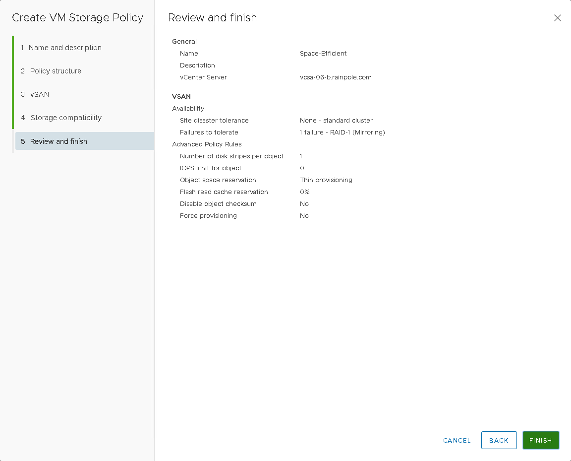
You can now inform the Kubernetes user of the storage policy name. The VM storage policy you created will be used as a part of storage class definition for dynamic volume provisioning.
Create a StorageClass
As a Kubernetes user, define and deploy the storage class that references previously created VM storage policy. We will use kubectl to perform the following steps. Generally, you provide the information to kubectl in a YAML file. kubectl converts the information to JSON when making the API request. We will now create a StorageClass YAML file that describes storage requirements for the container and references the VM storage policy to be used. The csi.vsphere.vmware.com is the name of the vSphere CSI provisioner, and is what is placed in the provisioner field in the StorageClass yaml. The following sample YAML file includes the Space-Efficient storage policy that you created earlier using the vSphere Client. The resulting persistent volume VMDK is placed on a compatible datastore with the maximum free space that satisfies the Space-Efficient storage policy requirements.
# cat mongodb-storageclass.yaml
kind: StorageClass
apiVersion: storage.k8s.io/v1
metadata:
  name: mongodb-sc
  annotations:
    storageclass.kubernetes.io/is-default-class: "true"
provisioner: csi.vsphere.vmware.com
parameters:
  storagepolicyname: "Space-Efficient"
  fstype: ext4
# kubectl create -f mongodb-storageclass.yaml
storageclass.storage.k8s.io/mongodb-sc created
# kubectl get storageclass mongodb-sc
NAME         PROVISIONER                    AGE
mongodb-sc   csi.vsphere.vmware.com   5s
Create a Service
As a Kubernetes user, define and deploy a Kubernetes Service. The Service provides a networking endpoint for the application. The following is a sample YAML file that defines the service for the MongoDB application.
# cat mongodb-service.yaml
apiVersion: v1
kind: Service
metadata:
  name: mongodb-service
  labels:
    name: mongodb-service
spec:
  ports:
  - port: 27017
    targetPort: 27017
  clusterIP: None
  selector:
    role: mongo
# kubectl create -f mongodb-service.yaml
service/mongodb-service created
# kubectl get svc mongodb-service
NAME              TYPE        CLUSTER-IP   EXTERNAL-IP   PORT(S)     AGE
mongodb-service   ClusterIP   None         <none>        27017/TCP   15s
Create and Deploy a StatefulSet
As a Kubernetes user, define and deploy a StatefulSet that specifies the number of replicas to be used for your application. First, create secret for the key file. MongoDB will use this key to communicate with the internal cluster.
# openssl rand -base64 741 > key.txt
# kubectl create secret generic shared-bootstrap-data --from-file=internal-auth-mongodb-keyfile=key.txt
secret/shared-bootstrap-data created
Next we need to define specifications for the containerized application in the StatefulSet YAML file . The following sample specification requests one instance of the MongoDB application, specifies the external image to be used, and references the mongodb-sc storage class that you created earlier. This storage class maps to the Space-Efficient VM storage policy that you defined previously on the vSphere Client side.
Note that this manifest expects that the Kubernetes node can reach the image called mongo:3.4. If your Kubernetes nodes are not able to reach external repositories, then this YAML file needs to be modified to reach your local internal repo. Of course, this repo also needs to contain the Mongo image. We have set the number of replicas to 3, indicating that there will be 3 Pods, 3 PVCs and 3 PVs instantiated as part of this StatefulSet.
# cat mongodb-statefulset.yaml
apiVersion: apps/v1
kind: StatefulSet
metadata:
  name: mongod
spec:
  serviceName: mongodb-service
  replicas: 3
  selector:
    matchLabels:
      role: mongo
      environment: test
      replicaset: MainRepSet
  template:
    metadata:
      labels:
        role: mongo
        environment: test
        replicaset: MainRepSet
    spec:
      containers:
      - name: mongod-container
        image: mongo:3.4
        command:
        - "numactl"
        - "--interleave=all"
        - "mongod"
        - "--bind_ip"
        - "0.0.0.0"
        - "--replSet"
        - "MainRepSet"
        - "--auth"
        - "--clusterAuthMode"
        - "keyFile"
        - "--keyFile"
        - "/etc/secrets-volume/internal-auth-mongodb-keyfile"
        - "--setParameter"
        - "authenticationMechanisms=SCRAM-SHA-1"
        resources:
          requests:
            cpu: 0.2
            memory: 200Mi
        ports:
        - containerPort: 27017
        volumeMounts:
        - name: secrets-volume
          readOnly: true
          mountPath: /etc/secrets-volume
        - name: mongodb-persistent-storage-claim
          mountPath: /data/db
      volumes:
      - name: secrets-volume
        secret:
          secretName: shared-bootstrap-data
          defaultMode: 256
  volumeClaimTemplates:
  - metadata:
      name: mongodb-persistent-storage-claim
      annotations:
        volume.beta.kubernetes.io/storage-class: "mongodb-sc"
    spec:
      accessModes: [ "ReadWriteOnce" ]
      resources:
        requests:
          storage: 1Gi
# kubectl create -f mongodb-statefulset.yaml
statefulset.apps/mongo created
Verify that the MongoDB application has been deployed. Wait for pods to start running and PVCs to be created for each replica.
# kubectl get statefulset mongod
NAME     READY   AGE
mongod   3/3     96s
# kubectl get pod -l role=mongo
NAME       READY   STATUS    RESTARTS   AGE
mongod-0   1/1     Running   0          13h
mongod-1   1/1     Running   0          13h
mongod-2   1/1     Running   0          13h
# kubectl get pvc
NAME                                        STATUS   VOLUME                                     CAPACITY   ACCESS MODES   STORAGECLASS   AGE
mongodb-persistent-storage-claim-mongod-0   Bound    pvc-ea98b22a-b8cf-11e9-b1d3-005056a0e4f0   1Gi        RWO            mongodb-sc     13h
mongodb-persistent-storage-claim-mongod-1   Bound    pvc-0267fa7d-b8d0-11e9-b1d3-005056a0e4f0   1Gi        RWO            mongodb-sc     13h
mongodb-persistent-storage-claim-mongod-2   Bound    pvc-24d86a37-b8d0-11e9-b1d3-005056a0e4f0   1Gi        RWO            mongodb-sc     13h
Set up the Mongo replica set configuration
To setup the Mongo replica set configuration, we need to connect to one of the mongod container processes to configure the replica set. Run the following command to connect to the first container. In the shell, initiate the replica set. You can rely on the host names to be the same, due to having employed the StatefulSet.
# kubectl exec -it mongod-0 -c mongod-container bash
root@mongod-0:/# mongo
MongoDB shell version v3.4.22
connecting to: mongodb://127.0.0.1:27017
MongoDB server version: 3.4.22
Welcome to the MongoDB shell.
For interactive help, type "help".
For more comprehensive documentation, see
        http://docs.mongodb.org/
Questions? Try the support group
        http://groups.google.com/group/mongodb-user
> rs.initiate({_id: "MainRepSet", version: 1, members: [
... { _id: 0, host : "mongod-0.mongodb-service.default.svc.cluster.local:27017" },
... { _id: 1, host : "mongod-1.mongodb-service.default.svc.cluster.local:27017" },
... { _id: 2, host : "mongod-2.mongodb-service.default.svc.cluster.local:27017" }
...  ]});
{ "ok" : 1 }
This makes mongodb-0 the primary node and other two nodes are secondary.
Verify Cloud Native Storage functionality is working in vSphere
After your application gets deployed, its state is backed by the VMDK file associated with the specified storage policy. As a vSphere administrator, you can review the VMDK that is created for your container volume.
In this step, we will verify that the Cloud Native Storage feature released with vSphere 6.7U3 is working. To go to the CNS UI, login to the vSphere client, then navigate to Datacenter → Monitor → Cloud Native Storage → Container Volumes and observe that the newly created persistent volumes are present. These should match the kubectl get pvc output from earlier. You can also monitor their storage policy compliance status.
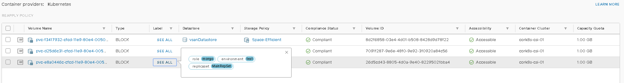
That completes the testing. CSI, CPI and CNS are all now working.